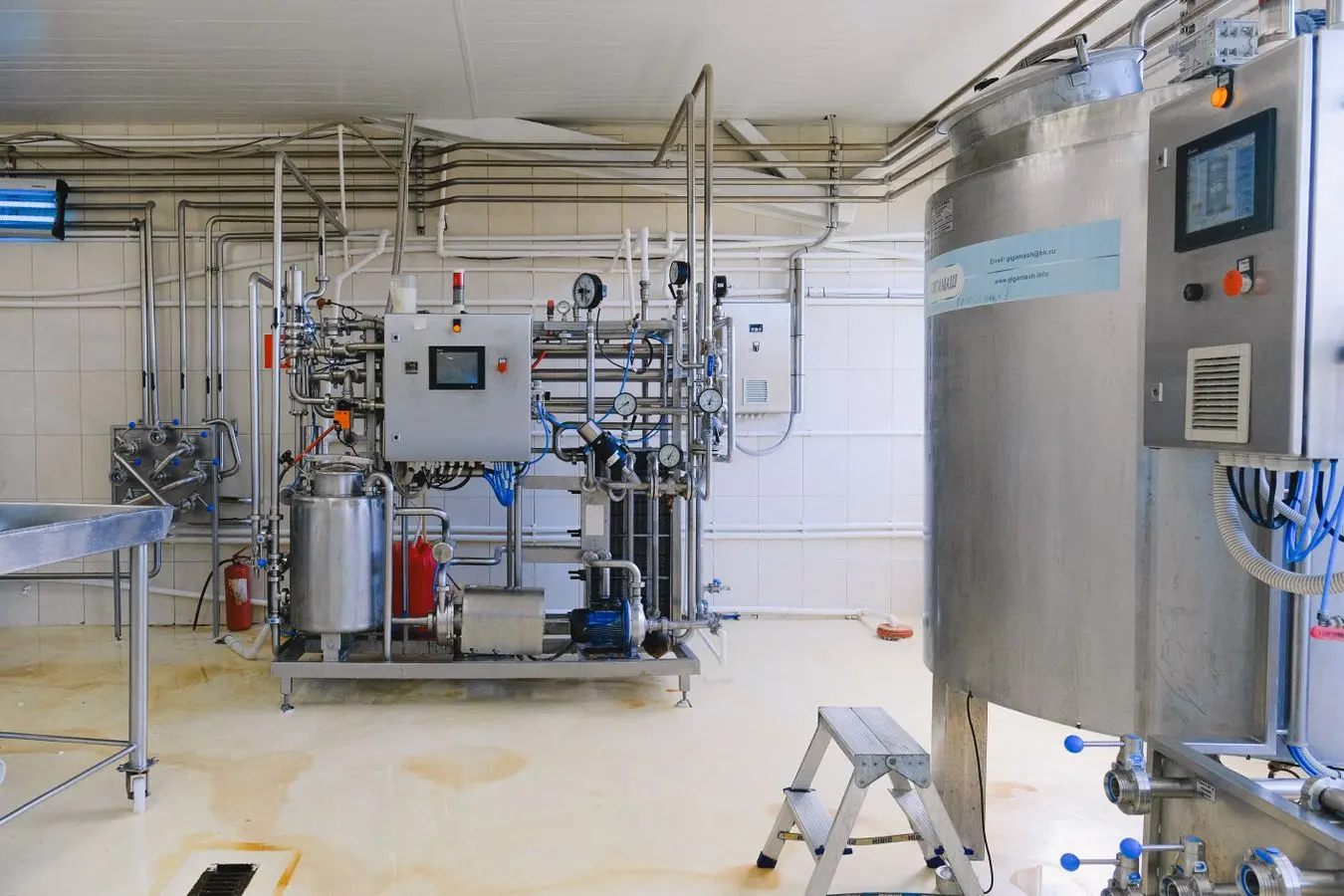
Moving heat rather than making it
A heat pump absorbs heat from a low-temperature source as refrigerant evaporates. A compressor raises the refrigerant pressure and temperature. The hot refrigerant then condenses and transfers heat to process water, air, oil or steam. An expansion device reduces pressure before the cycle begins again.
Electricity drives the compressor, pumps and controls. Because the delivered heat includes recovered source heat as well as electrical input, useful heat output can exceed electrical consumption by several times.
The two sides must match
The source might be condenser water from refrigeration, warm effluent, exhaust air, cooling water or ambient air. The sink might be wash water, pasteurisation, drying air, boiler feedwater or a steam header. Temperatures, flow rates and operating schedules are required on both sides.
A source that disappears when the sink needs heat creates a storage or backup requirement. A distant source introduces pipework and pumping losses. Contamination may require an intermediate heat exchanger.
Temperature lift governs the work
Temperature lift is the difference between the source level at the evaporator and the required delivery level at the condenser. A smaller lift generally supports a higher coefficient of performance. Process changes that reduce the sink temperature or raise the available source temperature can therefore be as important as equipment selection.
What changes across the heat exchangers
The source stream does not enter the compressor. It gives up heat across an evaporator, usually to a closed refrigerant circuit or an intermediate water loop. On the other side, the condenser transfers heat into the process circuit. This separation protects the refrigerant system from dirty effluent, food products, corrosive vapour and variable process pressure.
Every separation adds an approach temperature. If warm water leaves a process at 40°C, the refrigerant may need to evaporate several degrees below the return temperature. If the process needs 80°C water, the refrigerant must condense above 80°C. The compressor therefore bridges a wider lift than the simple difference between 40°C and 80°C.
Capacity changes with the duty
A heat pump does not have one fixed heating output. Capacity and power change with source temperature, sink temperature, flow and compressor speed. A machine selected for warm condenser water at one factory may deliver less heat when applied to a colder source or a hotter process return.
Manufacturer performance maps are needed for the expected operating range. The useful points include the coldest source, the highest required sink temperature, normal production, minimum stable load and any condition where the source or sink disappears. A maximum temperature in a catalogue is only an envelope limit.
Where the electricity goes
The compressor is normally the main electrical load. Source pumps, sink pumps, fans, oil systems, crankcase heaters and controls add to it. Project calculations should state whether these auxiliaries sit inside the quoted COP. The same boundary must be used when forecast performance is compared with metered performance.
Electrical input is also converted to heat and appears on the hot side. A system delivering 3 MW of useful heat at COP 3.0 uses about 1 MW of electricity and absorbs about 2 MW from the source. Both sides must be available at the same time.
Sources
Primary and authoritative sources used for the material claims on this page.